How to control Kato Unitrack, Tomix, and other turnouts with bi-directional solenoids using DCC, WCC, or DC.
In this guide, I'll show you how to control turnouts (or switches) with bi-directional solenoids using DCC (Digital Command Control), WCC (Wireless Command Control), or a web app. These turnouts have just two wires, and their direction changes depending on the current flow. For example, Kato and Tomix turnouts use bi-directional solenoids with only two wires.
We'll be using the Loco.Engineering accessory decoder and a DC motor driver, both of which you can order from our online shop. The Loco.Engineering accessory decoders allow you to control up to six turnouts via DCC, WCC, or directly from a web browser. Each DC motor driver can control up to two turnouts. So, to control six turnouts, you'll need one accessory decoder and three DC motor drivers (one motor driver per two turnouts).
Below is a schematic example showing how to connect a decoder, motor driver, and turnout. The wires from the track are optional if you want to control the turnout using WCC or directly from the web browser.
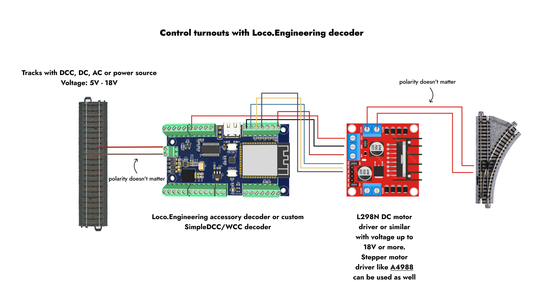
Connections:
- + (accessory decoder) -> VM (motor driver)
- GND (accessory decoder) -> GND (motor driver)
- +5V (accessory decoder) -> +5V (motor driver)
- IO7 (accessory decoder) -> ENA (motor driver)
- IO6 (accessory decoder) -> IN1 (motor driver)
- IO5 (accessory decoder) -> IN2 (motor driver)
- OUT1 (motor driver) -> Wire 1 (turnout)
- OUT2 (motor driver) -> Wire 2 (turnout)
After you’ve connected everything:
- Power the decoder using a USB Type-C cable or from the track. A red light should appear on the decoder.
- On your mobile device, tablet, or computer, open the list of Wi-Fi networks and join the network named loco-xxxxxx, where xxxxxx is the serial number of the decoder. If you only have one powered decoder nearby, this should be the only network with the loco-xxxxxx name, so you won’t need to check the serial number.
- Open a browser and go to
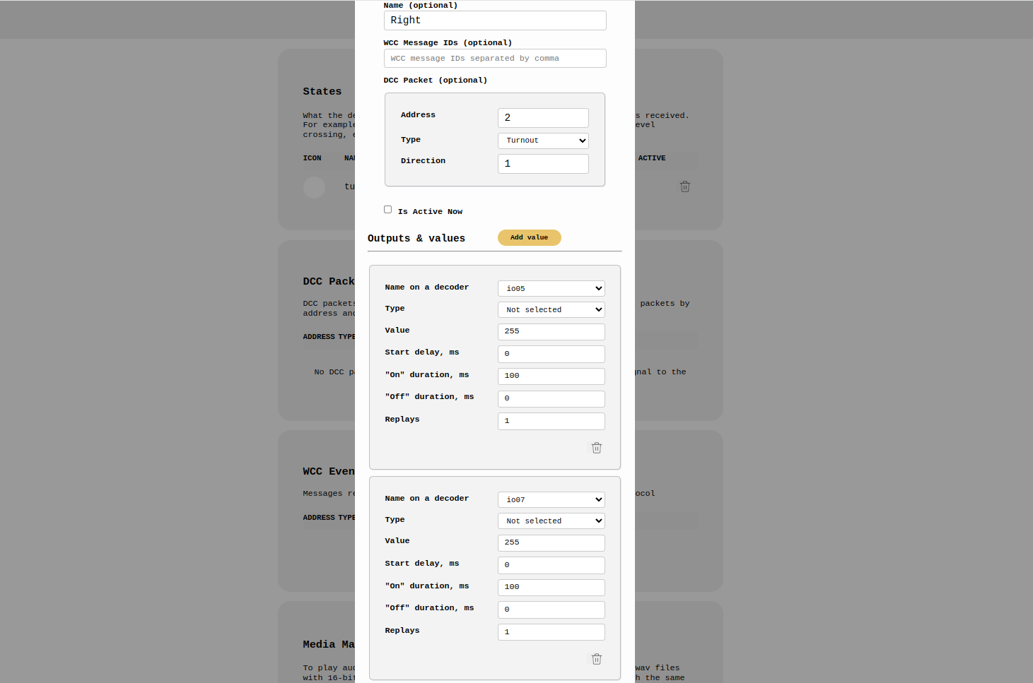
http://loco.localorhttp://192.168.4.1. - Scroll to the "States" section and click "Add state." A "State" defines what the decoder should do when it receives a DCC packet, a WCC message, or when a button in the web app is pressed.
- In the popup, you’ll see various settings for the new state. To change the turnout direction, current must flow through the turnout’s wires in two different directions, similar to reversing a brushed DC motor with two wires. This is why we need two states—one to send current from wire A to B, and the other from wire B to A. Configure both states as shown in the screenshots below and save them. In the DCC Packet settings, use the DCC address you plan to use with your command station. The decoder can use any DCC address.

That’s it—time to check if it works!
How to Control
- Using DCC: If you're using DCC, simply send a turnout DCC packet from your command station to the address you entered in the State settings.
- Without DCC: If you're not using DCC, scroll to the WCC Events section, click on "Send Event," enter the WCC Event ID from the State configuration screen, or select it from the dropdown, and click "Send."
Your turnout should change direction. Depending on the initial position, both DCC packets or WCC events may need to be sent to observe the change in direction.
Possible Issues
- Turnout doesn’t fully switch: If the turnout doesn’t switch completely, increase the duration of the state in the State configuration screen. Avoid setting a large duration, as it could damage the turnout. Start by adding 20, then try again. If it still doesn’t work, add another 20, and so on.
- Voltage too high: The voltage for the track or power source might be too high for the DC motor driver you're using.
- Turnout doesn’t respond to DCC packets or WCC events:
- Check all connections to ensure they are secure and correctly aligned as shown in the schematic.
- Verify that the decoder is powered and that the voltage is sufficient to switch the turnout. For example, if you’re powering the decoder with USB-C, some turnouts might not operate because they require more than 5V.
- Make sure you're using the same DCC address on both your command station and the State configuration screen when sending a DCC turnout packet. The same applies to WCC Event IDs.
If you continue to have issues, contact us at hey@loco.engineering. Please attach screenshots of your state configurations and describe your testing process.
Can I Install a Decoder Inside a Turnout?
Yes, you can use the tiny Loco.Engineering train decoder with a built-in DC motor driver as a built-in accessory decoder. This guide will work with the train decoder as well—the only difference is that you should solder the wires from the turnout to the M1 and M2 outputs and connect the power wires to the track. Additionally, in the State configurations, select "DC Motor" instead of IO outputs. All other steps in this guide remain the same.
What’s Next?
Check out our other guides on controlling signals, level crossing lights, servo and stepper motors, and detecting train locations with NFC readers. If you have any questions or feedback, contact us at hey@loco.engineering. We’re open to new ideas.