How to Control Model Railway Signals with DCC and WCC
This guide explains how you can control model railway signals and lights with DCC, WCC, or directly from a web browser using Loco.Engineering accessory decoders or custom-made decoders based on the SimpleDCC project.
In this guide, we’ll use a Polish Railway signal with 5 LEDs as an example. However, you can use signals from any country (Germany, France, Switzerland, the Netherlands, etc.) with up to 22 independent/grouped LEDs (representing up to 22 aspects). If your signal requires more than 22 independent LEDs, you can connect it to two decoders, allowing you to control up to 44 independent/grouped LEDs.
What You Need
- A Loco.Engineering accessory decoder (or a train decoder, if you plan to install it inside a turnout) or a custom-made SimpleDCC/WCC decoder
- A model railway signal or lights (we'll use this signal)
- A track with DCC/AC/DC, or a power source (e.g., USB-C)
Schematic
Below is an example schematic showing how to connect a decoder and signal. Right-click the image and select "Open image in new tab" to view it full-size. The track wires are optional if you prefer to control the turnout using WCC or directly via a web browser. The signal in this example has "+" and "-" connections for each LED.
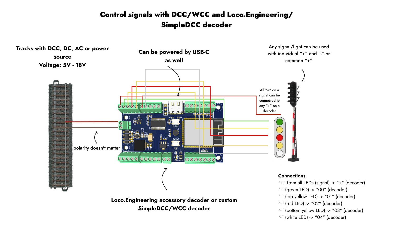
Loco.Engineering accessory decoders support signals with individual "+" and "-" for each LED, common "+", or common "-". If using ESP32S3 development boards, you can only use signals with individual "+" and "-" or a common "-".
You can map physical LEDs and aspects in the web app at any time.
Connections
- "+" from all LEDs (signal) -> "+" (decoder)
- "-" (green LED) -> "00" (decoder)
- "-" (top orange LED) -> "01" (decoder)
- "-" (red LED) -> "02" (decoder)
- "-" (bottom orange LED) -> "03" (decoder)
- "-" (white LED) -> "04" (decoder)
- (optional) Track wires with DCC -> "TRACK" (decoder)
The connections on the Loco.Engineering accessory decoder don't need to follow a strict order, as you can map the LEDs and aspects in the web app anytime. However, using outputs 00 - 15 is recommended, as these are controlled by an LED driver with a built-in resistor.
After Connecting Everything:
- Power the decoder using a USB Type-C cable or from the track. A red light should illuminate on the decoder.
- On your mobile device, tablet, or computer, open the list of Wi-Fi networks and connect to the network named loco-xxxxxx, where "xxxxxx" is the serial number of the decoder. If only one powered decoder is nearby, it should be the only network with the "loco-xxxxxx" name.
- Open a browser and navigate to http://loco.local or http://192.168.4.1.
- Scroll to the "States" section and click "Add state." A "State" defines what the decoder should do when it receives a DCC packet, a WCC message, or a button press in the web app.
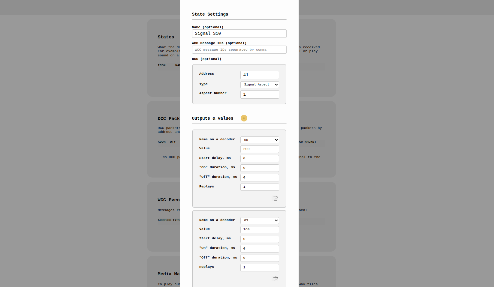
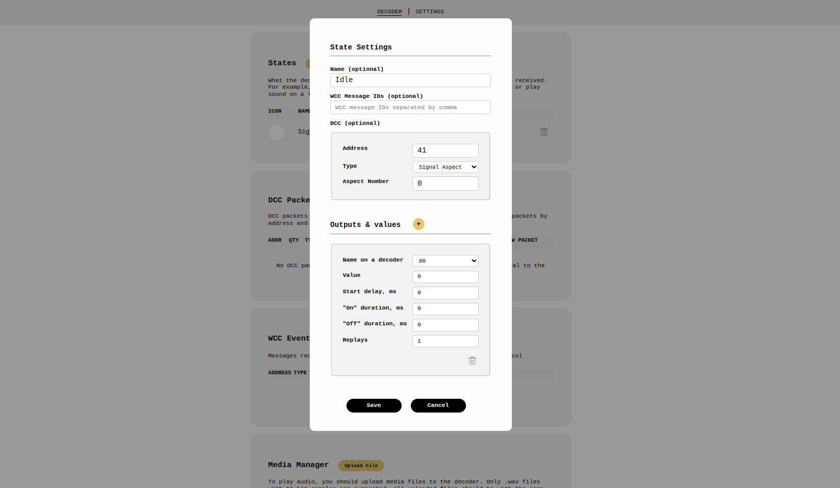
- In the popup, configure a state with an aspect (or group of LEDs) that should be on together and another state where all LEDs are off. For example, configure green and yellow LEDs to turn on when a DCC packet with address 41 and status 1 is sent (you can use any address and status in a DCC packet). Adjust the settings as shown in the screenshot below. To dim the LEDs, use values between 0 and 255 in the "Value" field. Ensure the DCC address matches the one in your command station (we'll use address 41 and aspect 1). Afterward, create another state to turn off the LEDs, using the same DCC address and DCC packet state 0 (see the second screenshot).
That's it! Now, test if it works. If using DCC, send a DCC packet to address 41 with state 1, and the green and yellow LEDs should light up. Send the same packet with state 0 to turn off all LEDs.
With SimpleDCC and Loco.Engineering, you're not limited to predefined aspects like with most accessory decoders—you can create any LED combinations.
How to Change Aspects or Turn LEDs On/Off
- Using DCC: Send an aspect DCC packet from your command station to the address specified in the State settings.
- Without DCC: Scroll to the WCC Events section, click "Send Event," enter the WCC Event ID from the State configuration screen, or select it from the dropdown, and click "Send."
The signal will display the aspect you defined in the State.
What's Next
Add as many aspects as you need. Keep in mind that a DCC aspect packet with one address can control up to 9 aspects. If you need more aspects, use multiple DCC packets with different addresses. For example, if you need 12 aspects on a signal, use two addresses—one for aspects 1-8 and another for aspects 9-12. If you have additional signs or LEDs, you can use another address for those. Loco.Engineering and SimpleDCC don't limit how many addresses one decoder can handle.
Possible Issues
Voltage too high: The voltage supplied to the track or power source might be too high for the DC motor driver you're using.
Signal doesn’t respond to DCC packets or WCC events: - Double-check all connections to ensure they're secure and aligned according to the schematic. - Ensure the decoder is powered and you're not using resistors with high-resistance signals. - Confirm you're using the correct DCC address in both your command station and the State configuration screen when sending a DCC turnout packet. The same applies to WCC Event IDs.
If problems persist, contact us at hey@loco.engineering. Please include screenshots of your state configurations and describe your testing process.
Questions?
Feel free to reach out to us at hey@loco.engineering.