Loco.Engineering DCC / WCC accessory decoder
Getting Started
Steps bellow are applied to Loco.Engineering decoders and custom decoders with SimpleDCC/WCC firmware.
- Power the decoder using USB-C, track power (DC or DCC), or any other power source. The allowed voltage range is 5V - 20V.
- Open the WiFi network list on a mobile device, laptop, or tablet and connect to the "locoxxxxx" network, where "xxxxx" is the serial number found on the bottom of the decoder.
- The easiest way to understand how the decoder works is to use the included test LEDs. Connect them to the decoder's LED outputs (the long leg is "+" and should be connected to the decoder's "+", while the short leg should be connected to any output from 00 to 15, see schematic below). You can also connect your own signals or LEDs. Note that some LEDs may require resistors; the test LEDs included with the decoder do not require resistors.
- After your device is connected to the decoder's WiFi and you've connected LEDs to the decoder, open a browser and navigate to http://loco.local or http://192.168.4.1 to access the web app where you can configure the decoder's settings and control it. While connected to the decoder's WiFi, your device won't have internet access, so you won't be able to open other websites.
- In the web app, click on "New state" to create a state for the connected LEDs. You can think of a state as a signal aspect or a condition of an element connected to the decoder that should be activated when a DCC packet or WCC message is received.
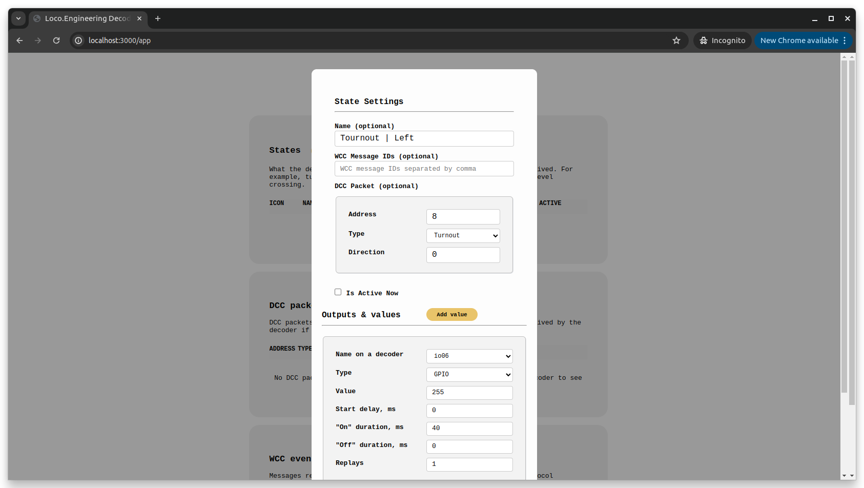
- Click "Test" to verify that the new state works correctly.
- (Optional) Send a DCC packet from the command station to test if the state is activated when a DCC packet is received.
- That's it! You can now add more states and control the decoder using DCC, WCC, or the web app.
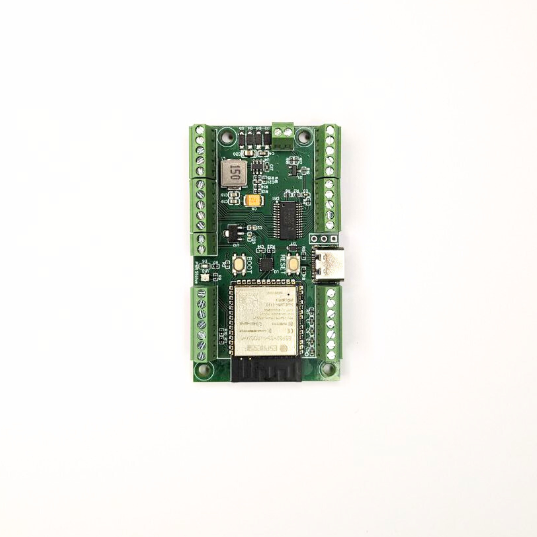
Loco.Engineering Accessory Decoder Specifications
- Dimensions: 67mm x 34mm x 8mm
- 16 outputs for LEDs and other loads that can be controlled by LED driver
- Max current per LED: 57 mA
- 8 outputs to connect servo motors and other components that can be controlled with PWM or digital signal (0 or 1)
- 8 inputs to handle interrupts from external devices
- Total current for servo motors: 1A
- Outputs with 5V, 3.3V and the same voltage as on tracks
- Works with DCC, WCC, and DC
- All decoder settings and logic can be updated over WiFi or USB, no command station and CV programming is required
- Fully programmable: use Arduino or ESP-Idf to develop custom firmware. Examples and friendly docs are available in our Knowledge Base
- Audio amplifier: 2W, 8Ω and outputs to connect a speaker
- USB type C port for flashing and updating decoder settings
- Flash Memory for sounds: 16MB
- RAM: 8MB
- I2C/SPI to connect NFC module, custom sensors, and DC motor extension board
- Operating Voltage: 5V - 20V
- Decoder CVs and logic can be updated without command stations directly from a web browser on a mobile phone, tablet, or laptop with a - WiFi/BLE connectivity
- Over-the-air updates with new features twice a month
Board Schematics
Custom firmware/code
Follow instructions on how to build and upload custom firmware at our GitHub repository
Questions?
Contact us at hey@loco.engineering