How to Build a Fully Automated Level Crossing for Your Model Railroad Layout with Lighting and Sound | Part 1
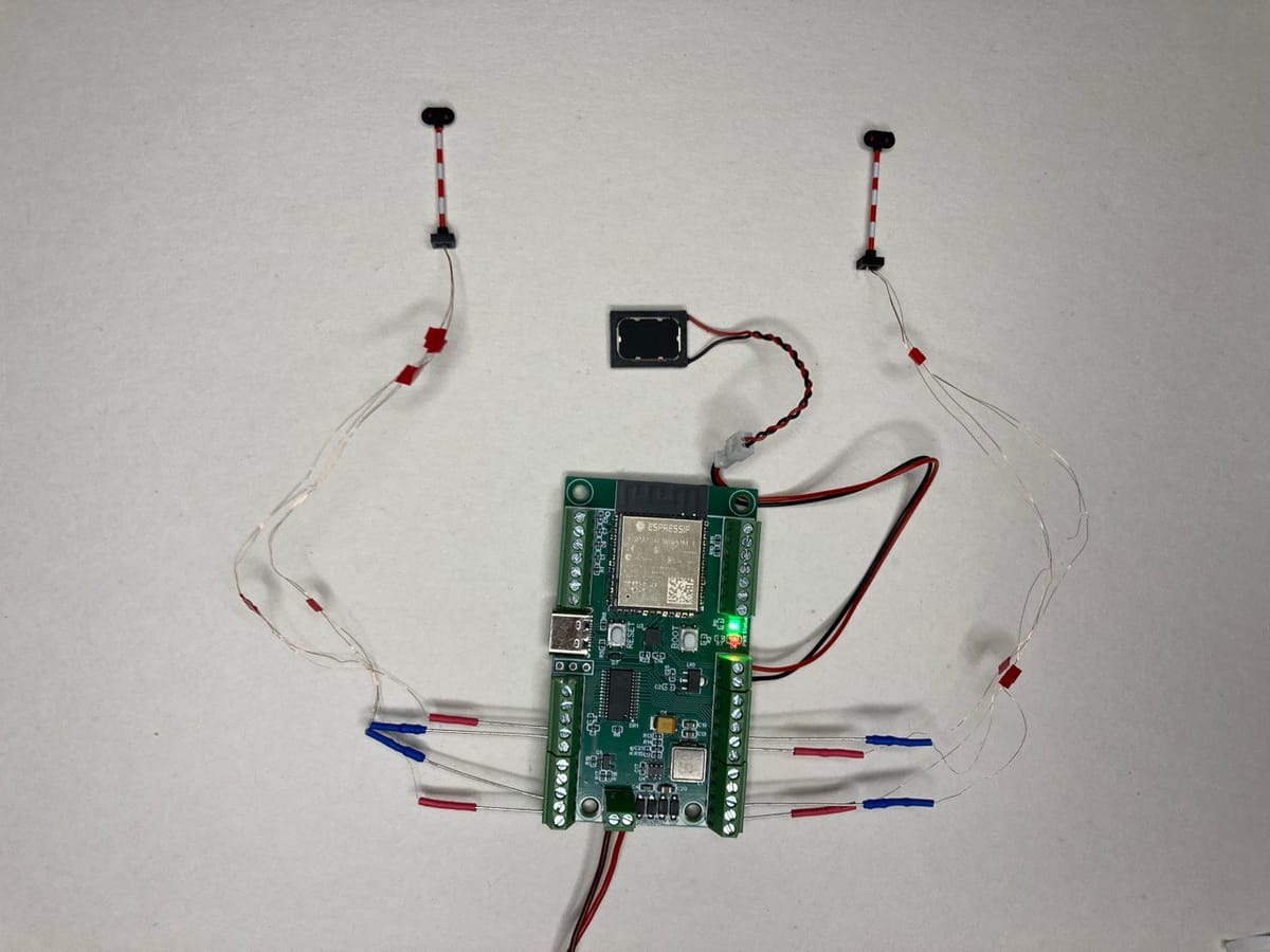
In this tutorial, I’ll show you how to create a fully automated level crossing for a model railroad layout or diorama. This setup works even without DCC and is compatible with small scales like N, TT, and H0. We’ll explore four different ways to control the level crossing:
- Using DCC (requires a DCC command station)
- Via a web browser
- By pressing a button mounted somewhere on your layout or module
- Fully automated: The level crossing activates when a train passes a specific point and deactivates when the train clears another point.
What You’ll Need
- Two level crossing signals
If you don’t have signals yet, you can use Loco.Engineering signals. Both common "-" and common "+" configurations will work, but this tutorial assumes signals with a common "+" as they are the most common. Signals with 1, 2, or 3 LEDs are compatible. - A speaker (optional)
Adding sound will enhance the realism of your layout. - A decoder
Use a Loco.Engineering accessory decoder or build your own decoder based on the ESP32S3 SoC. (You can find instructions for creating your own DCC accessory decoder here). - Track
Any brand will work (e.g., Märklin, Kato, Peco, Roco, etc.). - NFC readers and NFC tags
These can be ordered from the Loco.Engineering store. Alternatively, you can use other sensors capable of sending interrupts, like Hall sensors with magnets.
Note: If you only want to control the level crossing with DCC or a button and don’t need automation, NFC readers and tags are unnecessary. - Materials for housing electronics
Use cardboard or other materials to construct a box for electronics and to mount the signals.
Estimated Costs
The total estimated cost is around 80 EUR/85 USD, including signals, a decoder, and sensors (assuming you use Loco.Engineering components).
Tutorial Overview
This tutorial is divided into three parts:
- Part 1: Create a level crossing that can be controlled via a web browser or DCC.
- Part 2: Add a button for manual control.
- Part 3: Implement automation using NFC readers or other sensors.
In this first part, we’ll focus on the web browser and DCC control. By the end, your level crossing will be functional with sound (if a speaker is used) like on the video below:
Connections
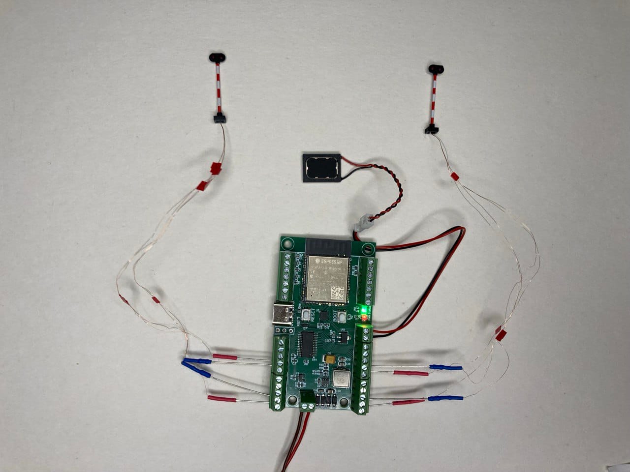
- Connect the Signal Wires
Signals I use for this tutorial have "+" and "-" wires for each LED. However, if your signals use a common "+" or "-", the setup will still work. Connect "-" of your signals to outputs 00-15 (in my case it will be 00, 04, 11, 15). "+" from LEDs should be connected to any "+" on a decoder. - Optional Speaker
To enhance realism, connect a speaker to the decoder’s "S+" and "S-" terminals. Speaker polarity doesn’t matter.
Your connections should resemble the photo below:
DCC Decoder Settings
- Power the Decoder
Use a USB-C cable or supply DCC/DC/AC power (up to 20V). A green status LED should light up. - Access the Decoder’s Interface
- Open the Wi-Fi settings on your device and connect to the "loco-...." network. The default password is "loco.eng".
- In a web browser, navigate to http://loco.local.
- Configure the Signal LEDs
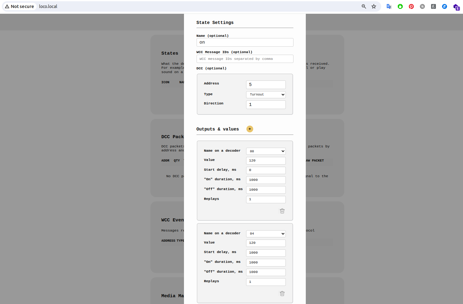
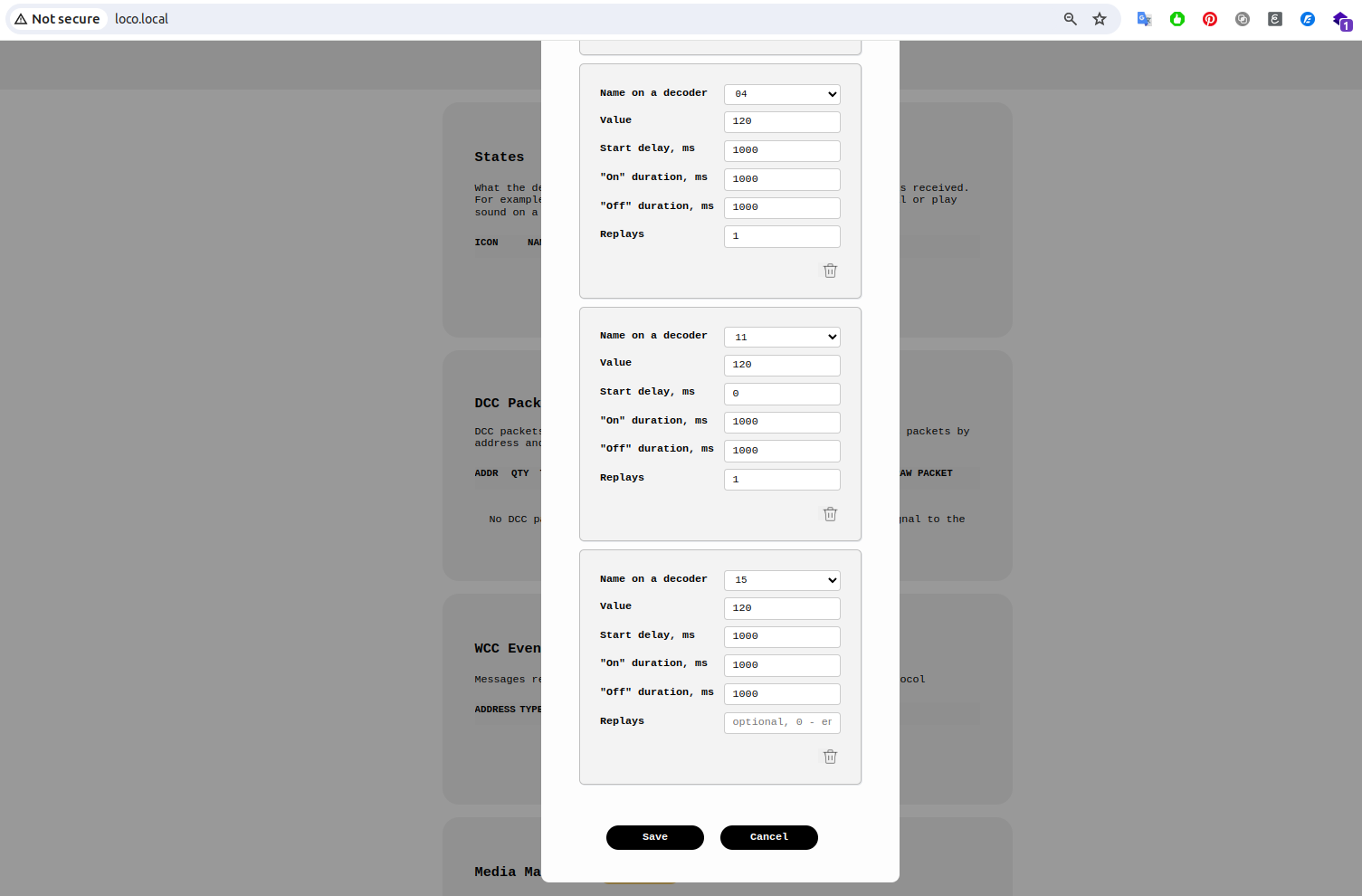
- Click on "Add Status" and configure the settings for the signal LEDs.
- For this example, I used turnout DCC packets with address 5:
- "On" is triggered by a DCC packet with direction "1".
- "Off" is triggered by a DCC packet with direction "0".
- You can use any DCC address and you can use an signal aspect DCC packet instead of turnout DCC packets.
My settings are shown below:
- Save and Test
Click "Save" and send a DCC packet to test the configuration. Your level crossing, complete with sound, should now be operational.
Next Steps
In Part 2, we’ll add a button to manually start/stop the level crossing "animation". In Part 3, we’ll implement automation using NFC readers ( you can replace NFC with other sensors capable of sending interrupts).
Questions?
If you have any questions, feel free to contact us at hey@loco.engineering.

