Tutorial: How to make an Arduino / ESP32 wireless DCC decoder?


- Level of Complexity: EASY
- Required time: 10 - 15 min
In this guide, you'll learn how to create your own wireless accessory or multifunction DCC decoder based on the ESP32S3 microcontroller and the SimpleDCC/WCC project.
Why should you build your own DCC decoder or use a programmable decoder?
Here are some key benefits:
Flexibility: You can implement complex control logic that's simply not possible with off-the-shelf decoders. This gives you unprecedented customization options.
No vendor lock-in: When you build your own decoder, you're not tied to any particular brand or manufacturer. You have complete freedom to choose the components and features that suit your needs.
Cost savings: Building your own decoder is often much more affordable than purchasing proprietary decoders from model railroad companies.
Repairability: If your custom-built decoder ever breaks, you can easily replace individual components inside it, rather than having to discard the entire unit.
Expanded capabilities: With a programmable decoder, you can connect all sorts of additional sensors and components, like NFC readers, stepper motors, displays, and more - things that aren't possible with typical commercial decoders.
In fact, many hobbyists find that once they experience the power and flexibility of a programmable decoder, they never want to go back to proprietary solutions. The customization and cost-savings are simply too compelling.
So if you're ready to take your model railroad control to the next level, let's dive into the steps to build your own wireless DCC decoder using the ESP32S3 and SimpleDCC/WCC project.
Components of a DCC/WCC decoder
Here are the key components needed to build your own DCC/WCC decoder:
- ESP32S3 Board: At the heart of your custom decoder will be an ESP32S3 system-on-chip (SoC). This powerful microcontroller has built-in Bluetooth, Wi-Fi, PWM capabilities, analog-to-digital converters, and over 30 I/O connections that can each handle up to 40mA of current - perfect for powering signals, lights, and other model railroad accessories.
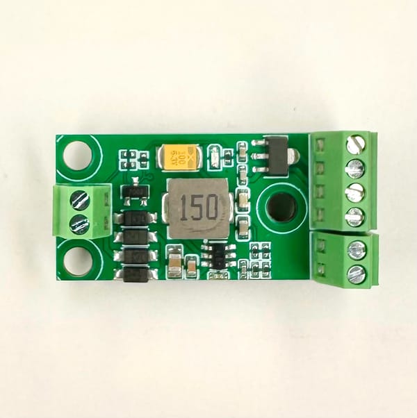
- DCC Converter (optional if you want to control the layout from the web app): To interface your ESP32S3 with the model railroad's DCC track power, you'll need a DCC converter circuit. This converts the alternating current (AC) from the rails into the direct current (DC) needed to power the microcontroller, while also converting the voltage changes on the rails into digital 0 and 1 signals that the ESP32S3 can understand. You have a couple options here - you can use a ready-to-use DCC converter circuit, or you can build your own using an optocoupler and rectifier bridge. If you choose to build it yourself, we've provided a schematic below that you can use as a reference (please note this schematic is only for non-commercial use).
- Firmware (or application) that will control elements connected to the decoder. We'll use the SimpleDCC/WCC project for Arduino - https://github.com/loco-engineering/simpledcc-arduino
- (Optional) A DC motor driver if you want to control a train, DC motors, or solenoids (for example, Kato turnouts use solenoids to change direction)
- (Optional) An LED driver if you need more than 40mA per LED
- (Optional) Digital-to-Analog converter and audio amplifier to play sound
- (Optional) Green connectors and/or a breadboard to avoid excessive soldering
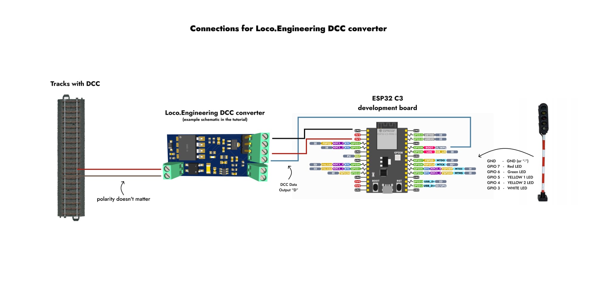
In this tutorial, we'll create a SimpleDCC decoder based on the ESP32-S3 development board, the Loco.Engineering DCC converter, and the SimpleDCC/WCC framework for Arduino. Alternatively, you can buy a ready-to-use programmable Loco.Engineering decoder that already has the ESP32-S3 SoC, DCC converter, and other features.
The decoder in this tutorial will control a Polish Railway signal, but you can use any other signal(s) you need. If you don't know how DCC works, be sure to check the related guide.
Don't worry if you've never programmed before - you can use the SimpleDCC/WCC project without writing any code, as the decoder logic can be updated directly in the web browser.
How SimpleDCC/WCC Differ from Other DCC Projects/Decoders
The main differences are:
- You don't need to understand DCC's inner workings because the decoder's logic can be set in the web app without additional programming tools.
- There's no need to study lengthy manuals. SimpleDCC performs actions (e.g., changing semaphore aspects, turning lights on/off) without strictly adhering to often ambiguous DCC protocols. You can view all messages received by a SimpleDCC decoder in your browser (with options to group and filter them), and define the decoder's response to received packets. In our experience, this greatly simplifies working with DCC.
- SimpleDCC decoders are compatible with virtually all command stations and DCC protocols (with mfx support on our roadmap). Even if you don't understand a DCC packet's format, you can still assign actions to it. For instance, Märklin Mobile Station sends accessory DCC packets in a non-standard format that most accessory decoders don't understand, but with SimpleDCC, you can assign actions to these packets as-is.
- SimpleDCC/WCC decoders can control trains, vehicles, and layout accessories like signals and turnouts without needing to know the specific types connected. With a traditional decoder, changing a signal aspect requires finding the correct command to send from the command station. With SimpleDCC/WCC, the user defines what action should occur when a specific DCC packet is received. You're not limited to predefined signal aspects or features set by manufacturers like Pico or Marklin. Instead, you can create virtually any state and action you need. No programming is required, but for advanced users, the source code is available for full control over the decoder's behavior.
- You can control almost everything with SimpleDCC/WCC from a command station or web browser, including RGB addressable LEDs, NFC readers, Hall sensors, servo motors, DC motors/single solenoids (an external DC motor driver is required) and more.
- SimpleDCC/WCC decoders can communicate with each other directly without any additional tools
Connections
If you use a Loco.Engineering decoder, you should connect it to the rails with DCC, and the signal should be connected to the decoder.
If you use your own ESP32-S3 board and a DCC converter, you should:
- Connect the ESP32-S3 board to the DCC converter
- Connect the DCC converter to the rails
- Connect a signal to the ESP32-S3 board
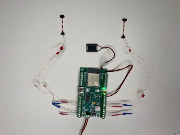
Example of connections in case you use an ESP32-S3 development board and Loco.Engineering DCC converter:
Upload SimpleDCC/WCC on a decoder
It's time to upload the SimpleDCC/WCC firmware to your DCC decoder. All the steps below will work only for ESP32-S3 boards, including Loco.Engineering decoders that are based on the ESP32-S3 as well.
How to upload the firmware to a SimpleDCC/WCC decoder:
- Download and install the Arduino IDE (Arduino is an application used to develop applications that can be launched on different microcontrollers).
- Install the ESP32 development tools for Arduino.
- Follow the instructions from the SimpleDCC/WCC repository on GitHub to install all the required frameworks.
- Upload the firmware to the decoder and reboot it.
- On your phone, tablet, or laptop, connect to the Wi-Fi network named
loco-xxxxx(by default, you should be able to connect without a password). - Open
http://loco.localorhttp://192.168.4.1in your web browser. - You should see the web-based configuration interface for the SimpleDCC/WCC decoder.
If the decoder is connected to the rails, you'll see the DCC packets in the web app (don't forget that you need a DCC converter that can transform the DCC signal from the rails into digital messages, convert the alternating current to direct current, and step down the voltage - do not connect your ESP32-S3 board directly to the rails).
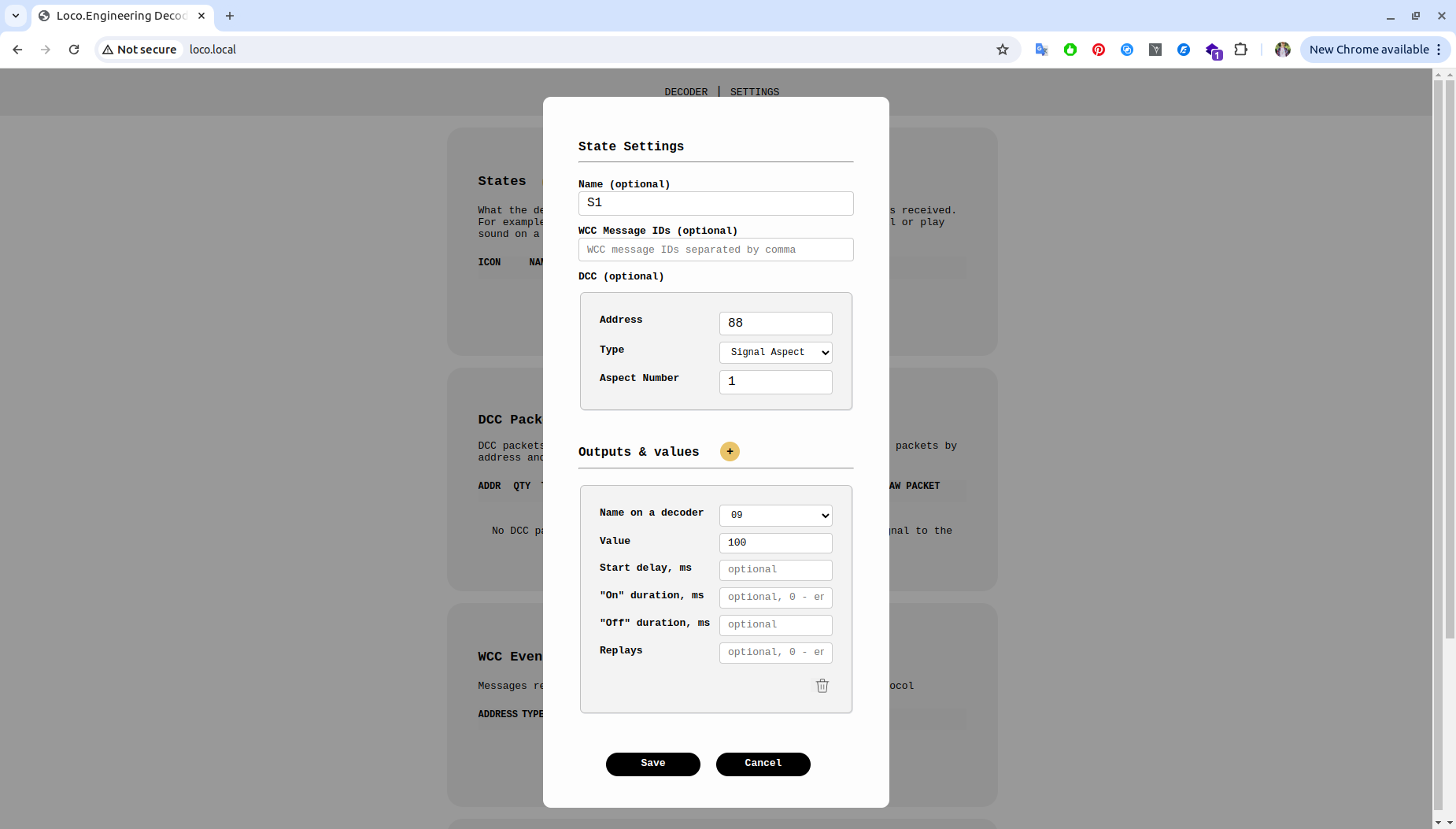
The idea behind SimpleDCC is to make DCC as simple as possible. That's why you shouldn't have to spend hours or even days reading through decoder manuals. To get your decoder working with your command station, you only need to complete two steps:
- Add an accessory or train decoder to your command station - use any decoder address, any port, and any function number.
- Add the decoder settings you used on the command station to your SimpleDCC/WCC decoder in the web app.
What features do we plan to add to Simple DCC?
This is the initial version of the SimpleDCC decoders for Arduino, but there are plans to add more features in the coming months. For example, the developers plan to add the following capabilities between September and December 2024:
- NFC readers to get information about train locations
- Support for stepper motors
- Ability to play media files, including video, on small displays
Feel free to contact the developers at hey[at]loco.engineering if you have any ideas about what should be added to the SimpleDCC/WCC Arduino project.
If you need ready-to-use or programmable decoders with features like sound, DCC decoder, LED drivers, and motor drivers, you can check out the Loco.Engineering decoders.